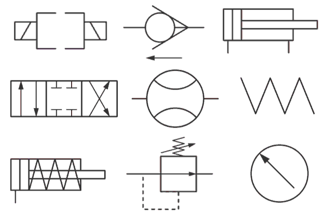
Hydraulic Symbols Schematic
What’s the difference between hydraulic circuit symbols? Figure c-2. hydraulic schematic (sheet 7 of 8) Hydraulic symbols
Figure C-2. Hydraulic Schematic (Sheet 7 of 8)
Hydraulic symbols circuit system common components Hydraulic schematic symbols tm sheet figure Systems power fluid hydraulic symbols system schematic valve pump diagram instrumentationtools components pumps these working compressor air symbology filter industrial
Hydraulic difference between valves machinedesign circuits instrumentation operated
Fluid power systemsHydraulic valves servo symbology fluidpowerworld operated response Hydraulic symbology 302 – high response valves.
.


hydraulic symbols

What’s the Difference Between Hydraulic Circuit Symbols? | Machine Design

Fluid Power Systems | Hydraulic System Working | Instrumentation Tools

Figure C-2. Hydraulic Schematic (Sheet 7 of 8)